Pennine CO2 (and other) pumps
Posted: Tuesday 16th June 2020
The Pennine CO2 pump was quite high-tech when it was introduced in the early 50’s (first catalogued in Holdsworth’s Aids between 1949 and 1952) compared with the celluloid pumps and rubber connectors on offer at the time. It was designed and manufactured by Geoff Wood who later became a partner in Whitaker and Mapplebeck in 1952 when Geoff Whitaker moved to Bristol. Gradually the W & M name was phased out and the company became Pennine Cycles although Johnnie Mapplebeck was still a partner and involved in the business in Bradford for many years.
“Medium height, balding, steel-framed specs, and an unexpectedly high Bradford voice. Nothing about Geoff looked heroic, but he was more than useful on a bike. For his ‘Pennine Accessories’ team, as it was in those BLRC days, he employed the seriously-good Manchester Independents Bevis Wood and Trevor Fenwick for stage races, and completed the team himself. Geoff wasn’t their equal, but he was no make-weight either”, says James Shaw who knew many of the cyclists in the Bradford area.
“Geoff had been apprenticed to Parkinson’s engineers in Shipley. They were a self-contained medium-sized family manufacturer of vices and machine tools, with their own foundry, so he was able to learn engineering from A-Z, which he clearly did.
Later, Geoff started making various accessories in a small workshop down an alley off Manningham Lane, Bradford, the main road to Keighley. How he ferreted out such places I don’t know. I can remember the aluminium bodies and levers of the CO2 pumps, and tools to speed their production. He employed an off-duty milkman and a pupil from nearby Belle Vue school who brought along a mate or two, all on an ‘informal’ basis. Someone talked, because the taxman paid a visit. How or where production continued after that I do not recall. The tie-up with Whitaker & Mapplebeck came later.” (Thanks to James Shaw for these memories of Geoff Wood – much more in Reminiscences).
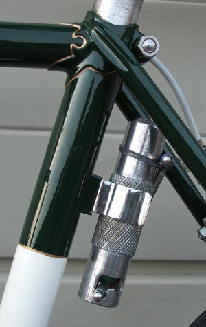
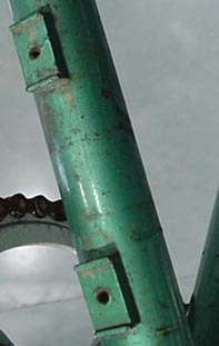
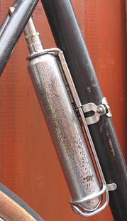
Below are details of the CO2 pump showing the way it was mounted when fitted to a frame with the special brazed-on ‘boss’. This is in 1963. Some riders carried the pump in their pocket and others used a Terry’s spring steel clip – often fitting the pump near the bottom of the down tube. A case of fashion over sense as the pump was right in line with any mud, water or dirt thrown up by the front wheel. The earlier pumps had a milled area on the body for grip and were threaded to screw onto the valve. The later ones had two plastic ‘anti-slip’ bands and they were pushed onto the valve with a rubber washer inside the pump providing the seal.
The rubber ‘handle’ on the pump is very inclined to perish as can be seen from some of the images above. It is possible to replace this with a piece of 5mm plastic piping used, amongst other things, for aquariums. It is available at model shops, some hardware stores, and garden centres which have an aquatic centre. The piping will be a very tight fit so try squirting the handle end with hairspray and then forcing the piping on before it sets. This has been done to the pump on the Carpenter although you are only looking at the end.
He tells us, I grew up in Stockport and cycling was my “Open Sesame” to a world beyond that town. I was a Leaguer and along with others formed North Cheshire Velo and we belonged to the Manchester section of the BLRC. This was in the 50’s and we saw the start of the “Tour of Britain” series sponsored by the Daily Express.
I had a good friend called Roy Mitchell who had a custom built racing frame and light engineering business on Hillgate in Stockport. He didn’t get enough orders to earn a living building frames so the light engineering side of his business kept him going. I used to do drawings for him (I was a draughtsman) and also do machining part-time.
One of the products I helped make was the Pennine CO2 pump. I machined the spiked nozzle that penetrated the CO2 Cylinder, used a fly press to close the end of the Aluminium tube before machining the plastic sleeve grooves and the closed end. Then punched the ‘L’ slots for the handle plus all the other operations to final assembly. So that is where the pumps were made.
Roy had served his apprenticeship with L H Brookes in Manchester, had a brother Eric, who rode as an independent with (I think ) ITP Pools and he (Roy) also manufactured many parts for the lightweight cycle frame makers. A partial list would be :- cable eyes, gear lever bosses, seat stay ends, built-up rear brake bridges, Co2 pump bosses, drinking bottle bosses and gear cable pulley assemblies. He supplied such as Dawes, Viking, Claud Butler and Pennine Cycles to name just four, with these products.
I have lived in Australia for over 40 years and still ride my EA Boult which has a Roy Mitchell CO2 pump boss (but behind the seat tube, about three inches below the seat height adjusting bolt), brake bridge, drinking bottle boss and gear lever boss.
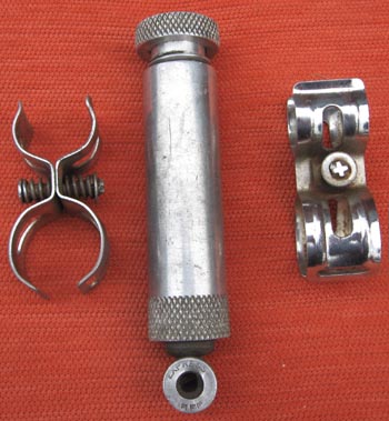
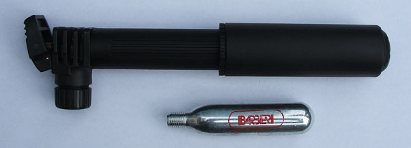
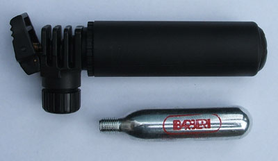
I acquired a Pennine Pump from fellow Redbridge CC member Alan Dawson. It had accumulated the muck from roads and garages over the years so I dismantled it to clean it thoroughly and possibly to replace the rubber seal to the valve neck. The construction is very simple but was something of a fiddle to dismantle before I had established how it was made!
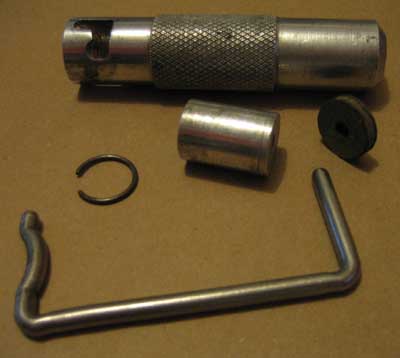
1. The aluminium body – is bored internally to accept the Sparklets bulb; the closed end has a hole drilled for the valve stem to pass; slotted holes are cut in the tubular walls near the open end to accept the actuating lever; internally a groove is cut in the tubular wall about 70mm from the open end.
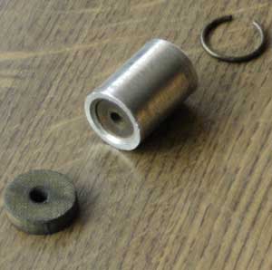
2. A rubber washer, approximately 5mm thick and 20mm diameter with a central hole and the surface texture of a standard tap washer (Image 2), slides down the tube to the drilled bottom.
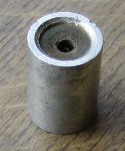
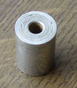
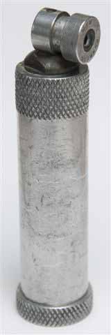
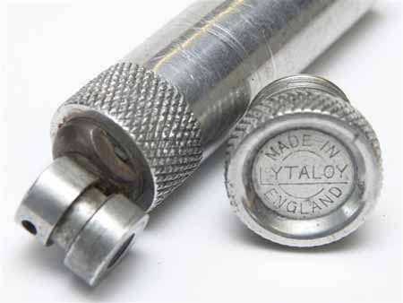
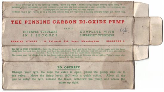
3. A piece of aluminium rod, approximately 27mm long and 20mm diameter (Images 1. 2 & 3), slides in next. This piece of rod has a few clever details: The end slid into the pump first is drilled approximately 6mm diameter x 12mm deep to clear the valve neck (Image 3) ; the other end of the rod is counter bored to accept a small diameter tap washer (Image 1 & 2) about 15mm diameter and the rim peined to retain the washer; visible through the centre of this washer and from the other end, is a small hardened steel tube of about 2mm outside diameter – I assume its pressed into a pilot hole.
4. The circlip (Image 2) slides in next to seat in the undercut groove and retain the parts.
5. A Sparklets bottle drops neck first into the pump and is retained with …
6.The bent (Stainless Steel?) actuator rod (above Right).
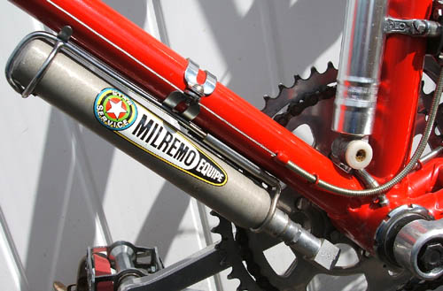
Milremo, one of the trading names of Ron Kitching, also produced a compressed air pump which was sold with a steel ‘cradle’ and longer than the Pennine at 23cm (9″). It was filled with nitrogen and had to be sent back to Kitching to be refilled (as did the Edco pump below). Here it is seen fitted below the down tube of a road racing frame owned by John Spooner. This was the positioning used by a lot of the road racing fraternity although the Pennine bosses were more often behind the seat tube, near to the top. This higher position, of course, kept the pump out of the mud, water and grit which would be thrown up by the front wheel.
Here, is the Edco pump in an Edco cradle, mentioned above, fitted to one of Mark Stevens’ Gillotts. It can be seen that the Milremo was ‘badge-engineered’ from this pump ,which in this case is mounted behind the seat tube just below the seat cluster. On the right is another of Mark’s Gillotts with twin ‘Pennine’ braze-on bosses mounted under the down tube near the bottom bracket (this position, along with behind the seat tube just below the seat cluster were the favourites). Although these are Pennine bosses they are obviously intended for use with a longer Milremo or Edco pump.
Posted: Tuesday 16th June 2020
This article appears in the following categories.
Upcoming Events
Whether you are looking for a gentle social meet up, or a 100-mile ride browse the community’s upcoming events and plan your next weekend outing.
